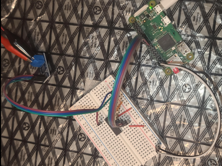
Using a Pi Zero W with a sensor to read battery voltage.
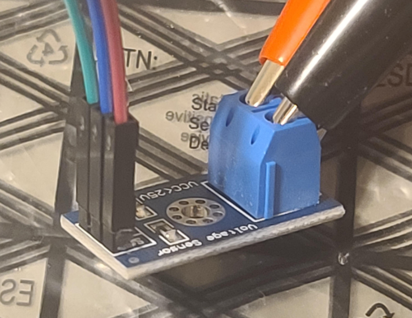
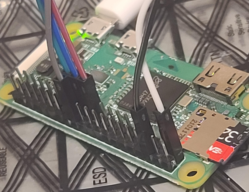
Sensor, board, and pi
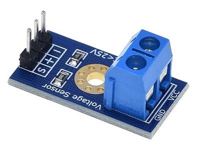
Voltage sensor: https://amzn.to/3AuDScb
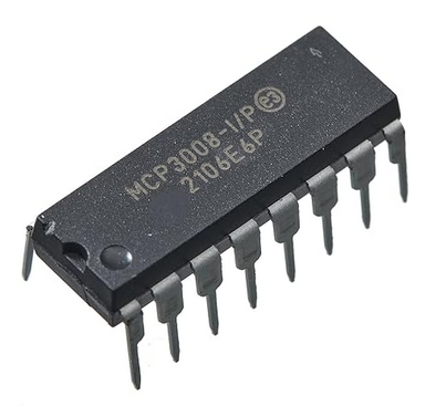
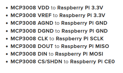
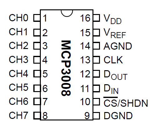
The famous serial to digital converter: MCP3008 that’s actually easy to set up:
The board:
Voltage sensor:
Pi Zero W:
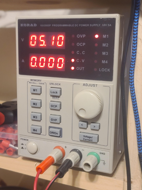
Lab power supply for testing:
Exact wiring instructions:
Wiring source: https://learn.adafruit.com/raspberry-pi-analog-to-digital-converters/mcp3008
Another great tutorial:
Hardware SPI (not Software SPI):
My notes:
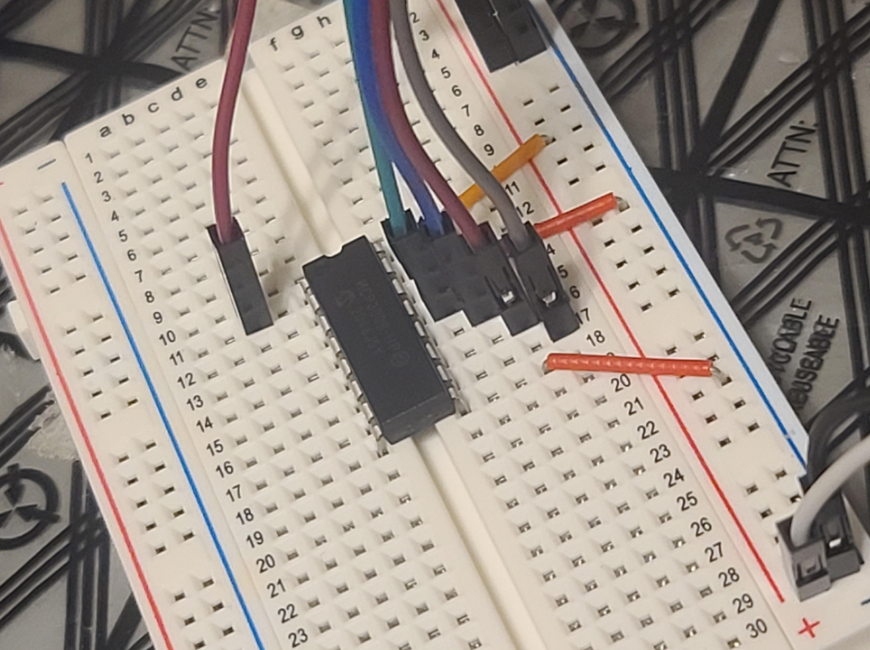
Left side:
MCP3008 pin 1 (channel 0) to Voltage S pin, sensor pin
MCP3008 pin 2 (ch1) to pin 8 (ch 7) unused in my setup
----
Right side:
MCP3008 pin 16 VDD to 3.3V rail
MCP3008 pin 15 VREF to 3.3V rail
MCP3008 pin 14 AGND to Ground 0V rail
MCP3008 pin 13 CLK to Raspberry Pi Pin 23 GPIO 11 (aka SPIO_CLK)
MCP3008 pin 12 DOUT to Raspberry Pi Pin 21 GPIO 9 (aka SPIO_MISO)
MCP3008 pin 11 DIN to Raspberry Pi Pin 19 GPIO 10 (aka SPIO_MOSI)
MCP3008 pin 10 CS/SHDN to Raspberry Pi Pin 24 GPIO 8 (aka SPI_CE0_N)
MCP3008 pin 9 DGND to Ground 0V rail
Reference:
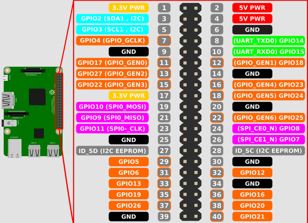
The following is a great YouTube tutorial, except he screws up and wires up Pi pin 22, which is incorrect — you need to wire Pi pin 24 instead. It’s a great tutorial though, check it out, both for Raspberry Pi and Arduino:
My setup that worked (August 2024)
# sudo raspi-config and enable SPI and reboot.
#
# Install libraries:
sudo apt-get install python3-pip

# create a sensors directory to work in
cd ~
mkdir sensors && cd sensors

# create a virtual environment
python3 -m venv .venv

# always run this after every reboot
source .venv/bin/activate

# install the drivers
pip3 install adafruit-circuitpython-mcp3xxx
pip install adafruit-mcp3008
The program that works: simpletest from https://github.com/adafruit/Adafruit_Python_MCP3008/blob/master/examples/simpletest.py
Here’s a copy, customized using hardware SPI, which you first enable and then reboot:
# Simple example of reading the MCP3008 analog input channels and printing
# them all out.
# Author: Tony DiCola
# License: Public Domain
import time

# Import SPI library (for hardware SPI) and MCP3008 library.
import Adafruit_GPIO.SPI as SPI
import Adafruit_MCP3008

# Hardware SPI configuration:
SPI_PORT   = 0
SPI_DEVICE = 0
mcp = Adafruit_MCP3008.MCP3008(spi=SPI.SpiDev(SPI_PORT, SPI_DEVICE))

print('Reading MCP3008 values, press Ctrl-C to quit...')
# Print nice channel column headers.
print('| {0:>4} | {1:>4} | {2:>4} | {3:>4} | {4:>4} | {5:>4} | {6:>4} | {7:>4} |'.format(*range(8)))
print('-' * 57)
# Main program loop.
while True:
    # Read all the ADC channel values in a list.
    values = [0]*8
    for i in range(8):
        # The read_adc function will get the value of the specified channel (0-7).
        values[i] = mcp.read_adc(i)
    # Print the ADC values.
    print('| {0:>4} | {1:>4} | {2:>4} | {3:>4} | {4:>4} | {5:>4} | {6:>4} | {7:>4} |'.format(*values))
    # Pause for half a second.
    time.sleep(1)
How it looks when it’s running:
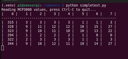
I’m using only channel 0 out of 7 (there are 8 in total), so column 0 is showing the analog to digital value.
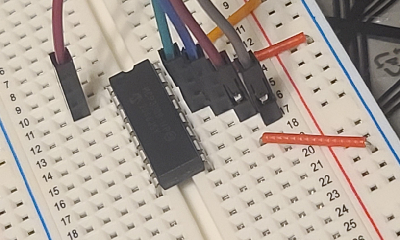
Reminder: it’s the top left pin for channel 0, my brown wire here:
Making sense of the numbers, I built a table of voltage supplied to the sensor, and the value the MCP3008 chip is reading, using the Adafruit library:
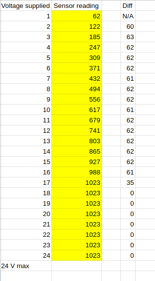
Notice that even though this sensor is rated to 24V max, I started getting a max sensor reading of 1023 when I reached about 17 volts, see table above.
It looks like the difference between 1 volt is about 62 sensor units, so the formula becomes:
Voltage = sensor_reading / 62
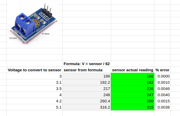
I tested some voltages and the live test matched the formula V = sensor / 62.
Pretty spot on voltage reading.
Next: TODO: make it all start up at boot on the pi zero w, set up a web interface to manage the readings, dump all readings to a system that graphs it all out.